Rotational Motion Mini-Lab.
Objectives.
1. Determine the acceleration of a block when released from a
pulley system.
2. Using the relationship between linear and rotational acceleration,
determine the rotational inertia of the pulley.
pulley system.
2. Using the relationship between linear and rotational acceleration,
determine the rotational inertia of the pulley.
Materials.
- Pulley with a block.
- Motion detector below the mass to measure linear acceleration by collecting distance vs. time data.
Procedure.
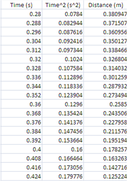
A pulley of unknown mass and radius of 0.0365 meters will be used in the lab experiment, as shown above. A small mass of 51.5 grams is attached to a string; the other end is attached to the pulley and wrapped around it several times. The block is released from rest, and distance vs. time data is collected with a motion detector CBL unit.
Data Analysis.
What quantities should be graphed in order to best determine the acceleration of the block? Explain your reasoning.
Distance should be plotted against time squared. This way the slope of the best fit line of the data points will be equal to one half of acceleration.
Plot the quantities determined in (1), title the graph, label the axes, and calculate the linear acceleration of the block. Use this acceleration and Newton’s second law for linear motion to find the tension in the string.
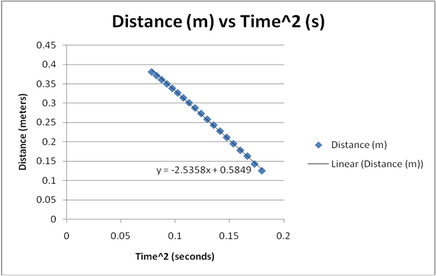
a=-2.5358*2=-5.0736m/s^2
T=mg-ma=.0515(9.81-5.0736)=.2439N
Derive an expression for the relationship between the linear acceleration of the block and the angular acceleration of the pulley and the tension in the string.
a=ar
T=mg-malpha
T=mg-m(alphar)
Sum t =Ialpha
T*r=Ialpha
I=(Tr)/alpha=(Tr)/(a/r)=(Tr^2)/a
Calculate the rotational inertia of the pulley.
I=(mg-ma)r^2/a
I=[(.0515*9.81)-(.0515*5.0736)](.0365)^2/5.0736=6.4044x10^-5
Is your answer reasonable? Why or why not?
As the disk was small and had the mass evenly distributed, it is reasonable that the rotational inertia is very small.
